
- Gotronik PPHU
NIP: PL8971671385 - E-mail:biuro@gotronik.pl
- TelefonBiuro: 71 351 10 31
Zamówienia: 511-048-814
Pyt, techniczne: 514-349-414 - Gadu Gadu1767965
5476656
8342724
- 1
Papier termotransferowy A4 do płytek drukowanych
- 2
Filtr 16,8mm do ZD915 ZD917 ZD-915 ZD-917
- 3
Przetwornica napięcia 12V Step Up
- 4
Moduł szufladki magazynowej z przegródkami 180x110x55mm
- 5
Krokodylek 2mm do przewodów miernika CZERWONY
- 6
Krokodylek 2mm do przewodów miernika CZARNY
- 7
Chwytak pomiarowy pazurkowy czerwony
- 8
Chwytak pomiarowy pazurkowy czarny
- 9
936DH stacja lutownicza ZHAOXIN
- 10
Grot N5-3 1,3mm (ZD917 ZD915) ZD-915 ZD-917

UT15C wskaźnik napięcia 12-690V AC/DC115,99 zł brutto94,30 zł netto

Kamera termowizyjna UTi260B rozdzielczość 256 x 1921 450,00 zł brutto1 178,86 zł netto
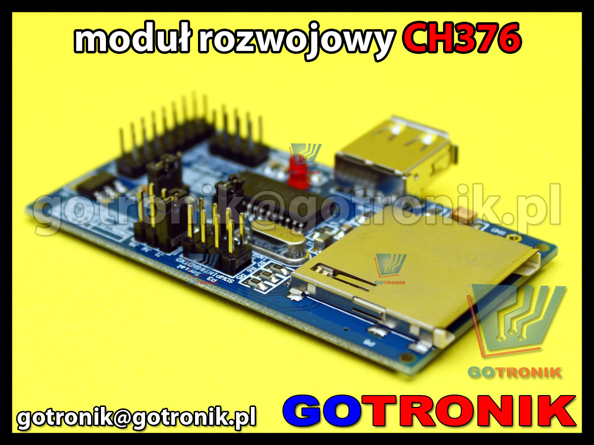
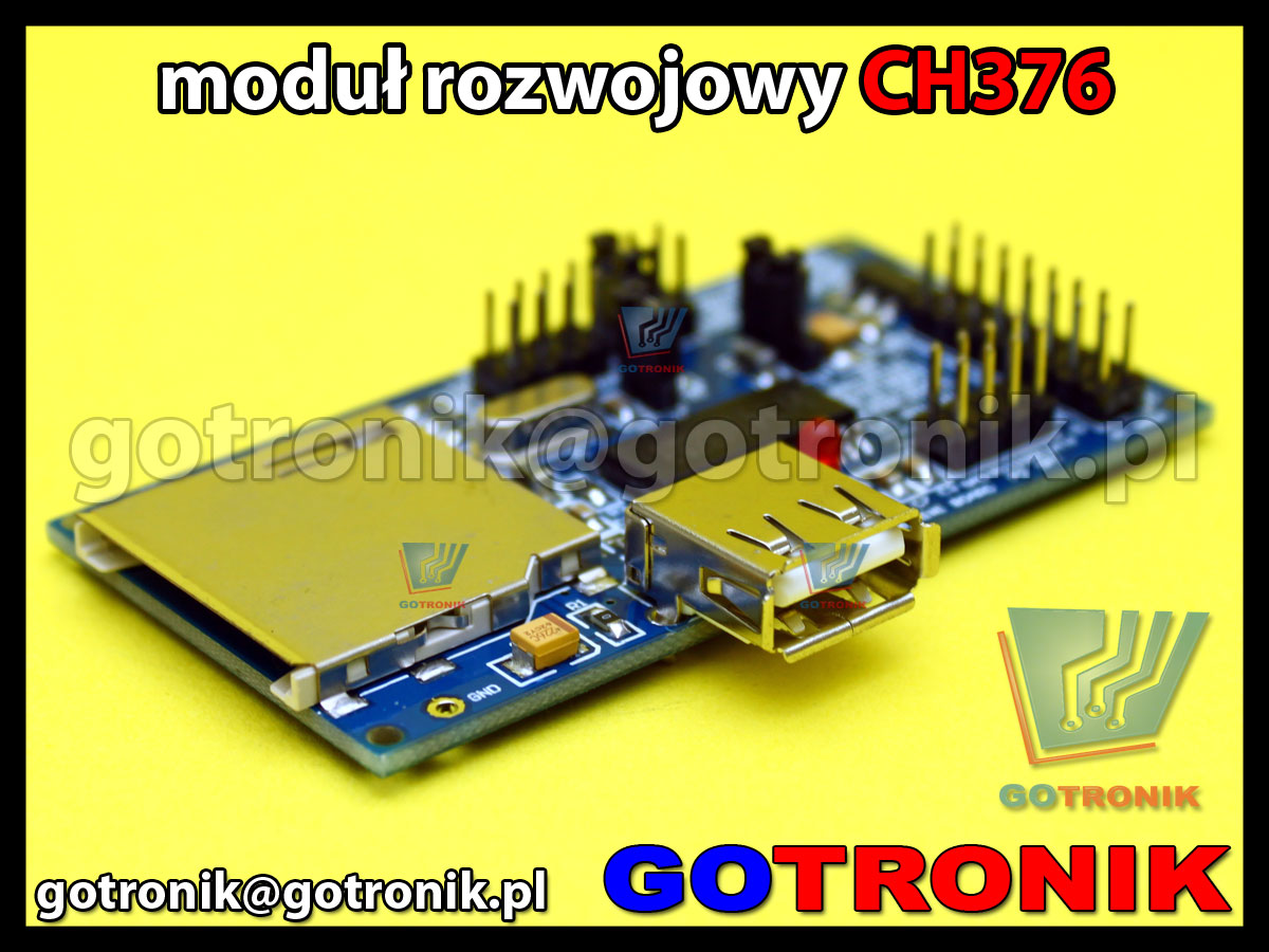
Zestaw rozwojowy CH376S USB - parallel/SPI/serial/UART
Dostępność: Niedostępny
Koszt wysyłki: od 11,99 zł
Numer katalogowy: LCT-009
Stan magazynowy: ![]()
- Opis produktu
- Recenzje produktu (0)
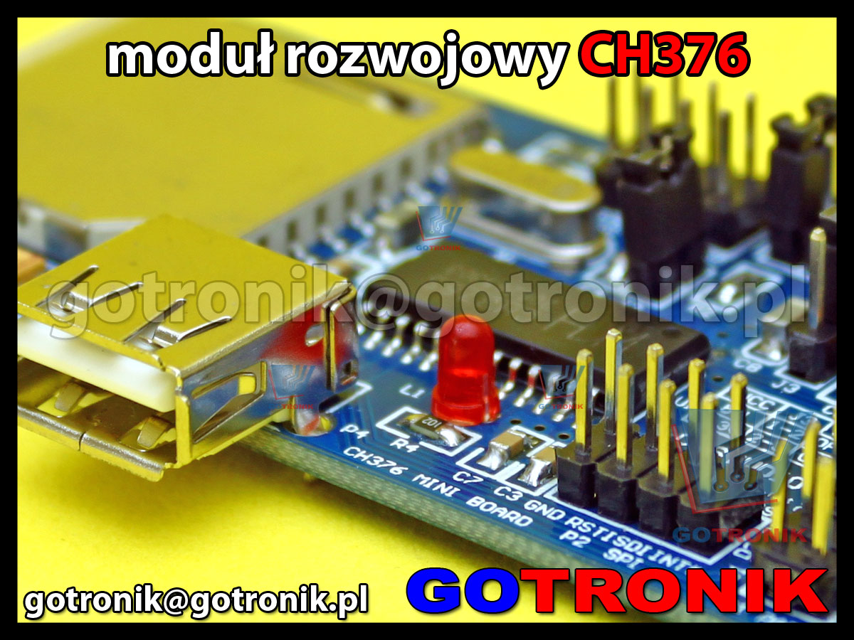
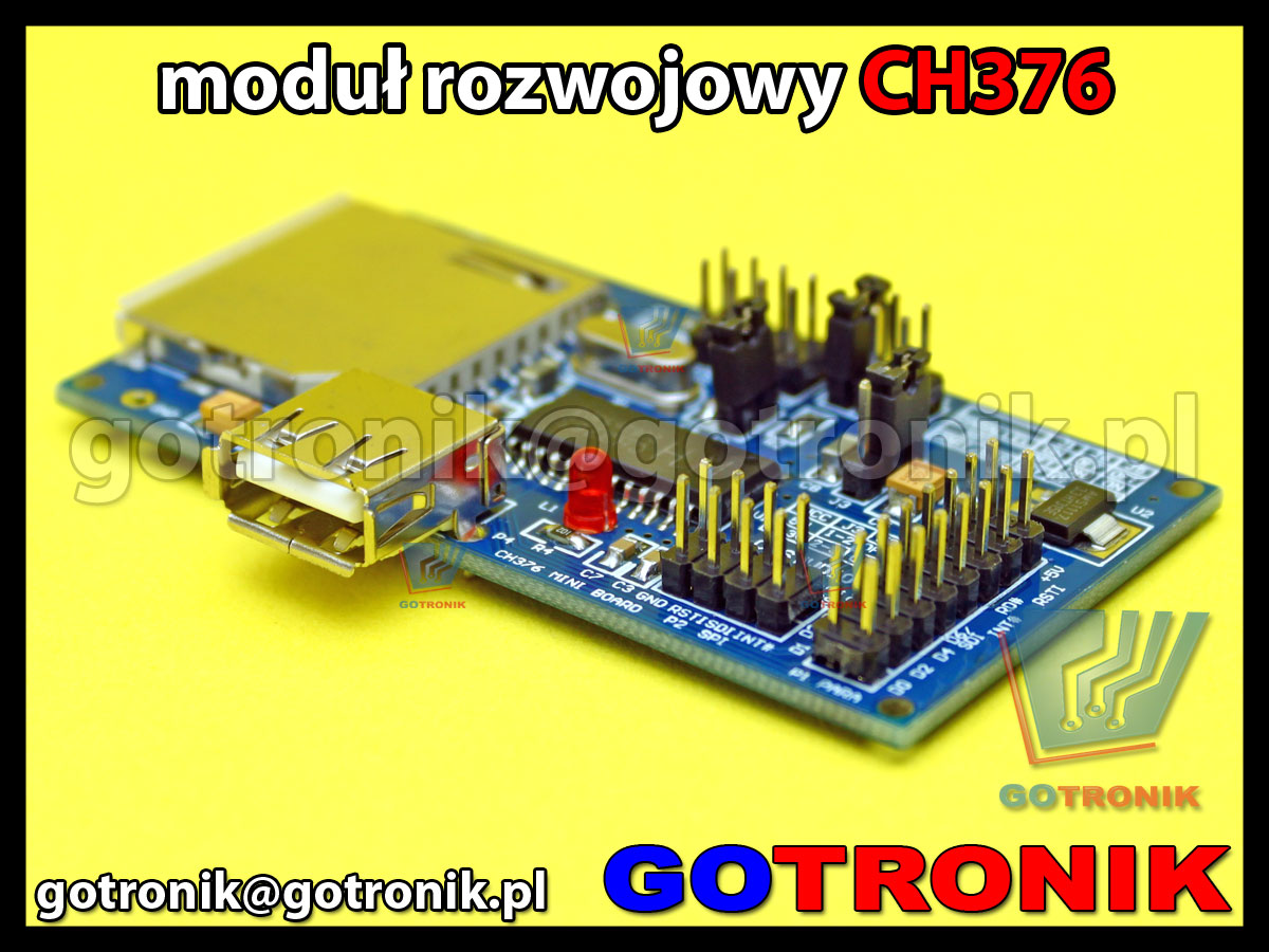
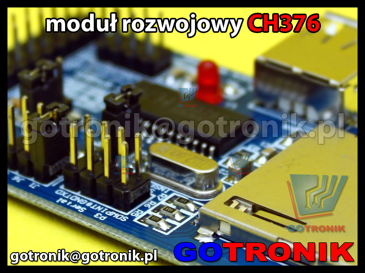
Zestaw rozwojowy CH376S przeznaczony jest dla układów mikroprocesorowych AVR, PIC, ARM, Arduino aby w łatwy procesor sterujący mógł być wykorzystywany do odczytu systemu plików odczyt/zapis na dysku USB Flsh lub na karcie SD. Konwerter USB na interfejs równoległy, UART/Serial, SPI.
Zestaw rozwojowy CH376S USB - parallel/SPI/serial/UART
Zestaw rozwojowy CH376S przeznaczony jest dla układów mikroprocesorowych AVR, PIC, ARM, Arduino aby w łatwy procesor sterujący mógł być wykorzystywany do odczytu systemu plików odczyt/zapis na dysku USB Flsh lub na karcie SD. Konwerter USB na interfejs równoległy, UART/Serial, SPI.
Doskonale nadaje się do pracy z mikrokontrolerami AVR, PIC, ARM oraz modułami Arduino.
-
CH376S jest używany jako kontroler sterujący, używany do systemów MCU przy zapisie/odczycie plików w pamięci USB lub na kartach SD-Card. CH376 obsługuje tryb USB-Device i tryb USB-HOST.
-
Protokołu komunikacyjny do współpracy z urządzeniami pamięci masowej, interfejsu komunikacyjnego firmware kart SD, FAT16, FAT32 i system plików FAT12. Obsługuje urządzenia pamięci masowej USB (USB Flash / twardy dysk USB Flash / USB / pamięci USB czyta karty) i SD (karty SD standardowej pojemności i karty SD HC o dużej pojemności, MMC i karty TF zgodny z protokołem).
-
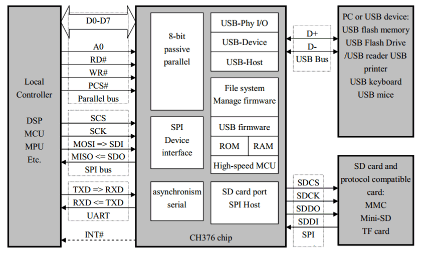
CH376 obsługuje trzy interfejsy komunikacyjne: 8-bitowy równoległy, interfejs SPI lub interfejs szeregowy asynchroniczny.
-
DSP / MCU / MPU kontroler itp. za pośrednictwem dowolnego interfejsu kontroluje układ CH376 do przechowywania i dostępu plików w pamięci USB lub karty SD, lub komunikacji z komputerem.
schemat blokowy układu CH376S:
Cechy układu CH376:
- wsparcie prędkości transmisji 1.5Mbps low-speed i 12Mbps full-speed
- kompatybilny z USB V2.0 (wymagany zewnętrzny oscylator kwarcowy)
- praca w trybie USB-HOST i USB-DEVICE , automatycznia przełączany tryb pracy
- wsparcie dla kontroli transferu USB
- automatycznie wykrywa podłączenie/odłączenie urządzenia USB i wysyła wiadomość do hosta USB
- wsparcie dla interfejsu SPI
- obsługuje karty SD, MMC i karty TFzgodne z protokółem
Arduino CH376 USB Host Shields
|
Instrukcja opis konfiguracji modułu CH376S:
|
Zdjęcia:



Nikt jeszcze nie napisał recenzji do tego produktu. Bądź pierwszy i napisz recenzję.
Tylko zarejestrowani klienci mogą pisać recenzje do produktów. Jeżeli posiadasz konto w naszym sklepie zaloguj się na nie, jeżeli nie załóż bezpłatne konto i napisz recenzję.


 karta katalogowa CH376