
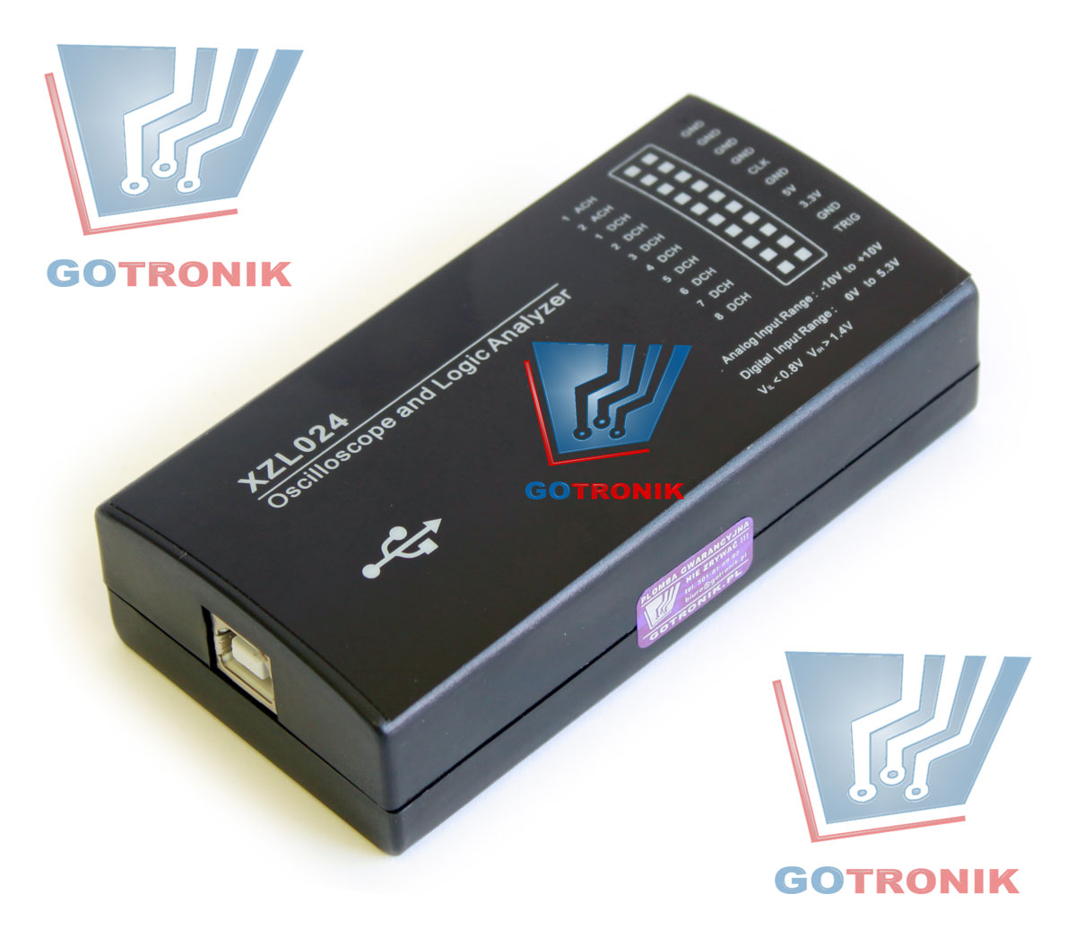
oscyloskop i analizator stanów logicznych
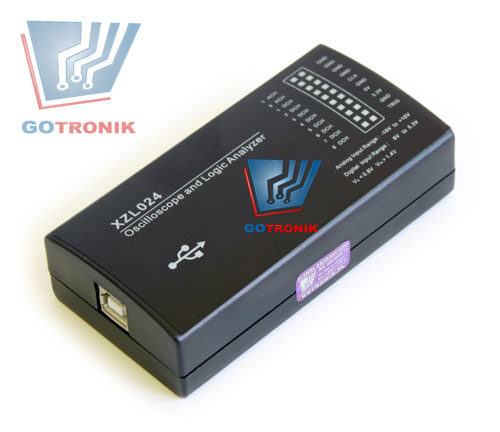
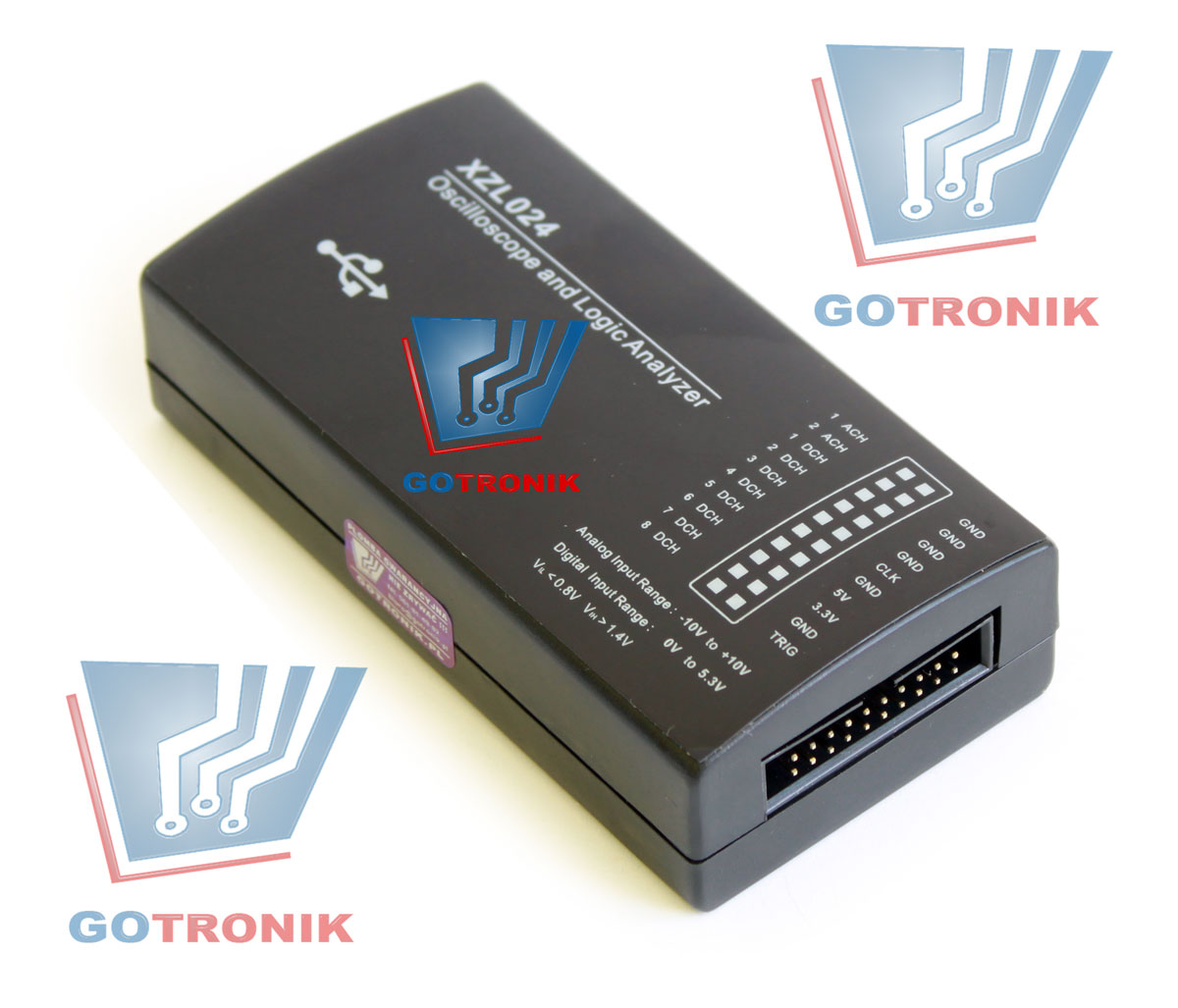
Oferowany interfejs USB XZL024 zbudowany jest w oparciu o mikrokontroler CY7C68013a produkcji Cypress. Możliwa jest współpraca urządzenia z oprogramowaniem USBee AX.
Urządzenie podłączane jest z komputerem za pomocą interfejsu USB 2.0 i wykorzystuje jego maksymalną prędkość transmisji, dzięki temu mamy możliwość wykorzystania zasobów komputera w celu przechwycenia i kontroli cyfrowych i analogowych informacji, transmisji.
Funkcje interfejsu:
-
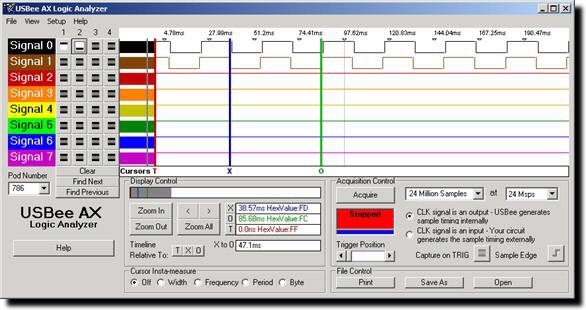
Oscyloskop cyfrowy z analizatorem stanów logicznych Mixed Signal Oscilloscope (MSO) Logic Analyzer and Oscilloscope
-
Oscyloskop cyfrowy
-
Analizator stanów logicznych
-
Dekoder popularnych protokołów
-
Generator cyfrowych sygnałów
-
PWM Controller
-
Remote Controller
-
Data Logger
-
Digital Voltmeter
-
Frequency Counter
-
Pulse Counter
Wybrane parametry:
-
Liczba analogowych kanałów: 2
-
Liczba cyfrowych kanałów: 16
-
Maksymalna częstotliwość próbkowania przy wykorzystaniu wszystkich kanałów: 8MSa
-
Maksymalna częstotliwość próbkowania przy wykorzystaniu 1 kanału: 16MSa
-
Długość rekordu: 200 + milion próbek – używa pamięci RAM / dysk twardy
-
Maksymalne napięcia wejściowe dla analogowych wejść: +/- 10V
-
Rozdzielczość przetwornika ADC: 8bit
-
Zakres napięć wejściowych dla wejść cyfrowych: 0-5V
-
Dekodery protokołów: In-Line Bus Decoders, USB Decoder, I2C, SPI, Async Decoder, CAN, I2S, 1-wire, SM Bus, PS/2, Serial Decoder, Parallel Decoder, Custom Decoder API, Bus Data Extractors
-
zasilanie interfejsu z portu USB
| Oscyloskop: |
|||||||||||||||||||||||||||||||||||||||||||||||||||||||||||||
 |
|
||||||||||||||||||||||||||||||||||||||||||||||||||||||||||||
Analizator stanów logicznych: |
|||||||||||||||||||||||||||||||||||||||||||||||||||||||||||||
|
 |
||||||||||||||||||||||||||||||||||||||||||||||||||||||||||||
Mixed Signal Oscope/Logic Analyzer |
|||||||||||||||||||||||||||||||||||||||||||||||||||||||||||||
 |
[1] Maximum sample rate depends on your PC hardware CPU speed and USB 2.0 bus utilization. For the fastest possible sample rates, follow these simple steps:
[2] Maximum buffer size depends on your PC available RAM at the time the application is started. |
||||||||||||||||||||||||||||||||||||||||||||||||||||||||||||
I2C Decoder Specifications |
|||||||||||||||||||||||||||||||||||||||||||||||||||||||||||||
|
 |
||||||||||||||||||||||||||||||||||||||||||||||||||||||||||||
Digital Voltmeter |
|||||||||||||||||||||||||||||||||||||||||||||||||||||||||||||
 |
|
||||||||||||||||||||||||||||||||||||||||||||||||||||||||||||
I2C Decoder Specifications |
|||||||||||||||||||||||||||||||||||||||||||||||||||||||||||||
|
 |
||||||||||||||||||||||||||||||||||||||||||||||||||||||||||||
Digital Signal Generator |
|||||||||||||||||||||||||||||||||||||||||||||||||||||||||||||
 |
|
||||||||||||||||||||||||||||||||||||||||||||||||||||||||||||
SPI Decoder Specifications |
|||||||||||||||||||||||||||||||||||||||||||||||||||||||||||||
|
|||||||||||||||||||||||||||||||||||||||||||||||||||||||||||||
Data Logger Specifications |
|||||||||||||||||||||||||||||||||||||||||||||||||||||||||||||
 |
|
||||||||||||||||||||||||||||||||||||||||||||||||||||||||||||
Frequency Counter |
|||||||||||||||||||||||||||||||||||||||||||||||||||||||||||||
|
 |
||||||||||||||||||||||||||||||||||||||||||||||||||||||||||||
Remote Controller |
|||||||||||||||||||||||||||||||||||||||||||||||||||||||||||||
 |
Remote Controller Specifications
|
||||||||||||||||||||||||||||||||||||||||||||||||||||||||||||
PWM Controller |
|||||||||||||||||||||||||||||||||||||||||||||||||||||||||||||
|
 |
||||||||||||||||||||||||||||||||||||||||||||||||||||||||||||
Frequency Generator |
|||||||||||||||||||||||||||||||||||||||||||||||||||||||||||||
 |
|
||||||||||||||||||||||||||||||||||||||||||||||||||||||||||||
I2C Controller |
|||||||||||||||||||||||||||||||||||||||||||||||||||||||||||||
|
 |
||||||||||||||||||||||||||||||||||||||||||||||||||||||||||||
Pulse Counter |
|||||||||||||||||||||||||||||||||||||||||||||||||||||||||||||
 |
|
||||||||||||||||||||||||||||||||||||||||||||||||||||||||||||
usbee ax pro opinie xzl024 http://www.usbee.com/ax.html
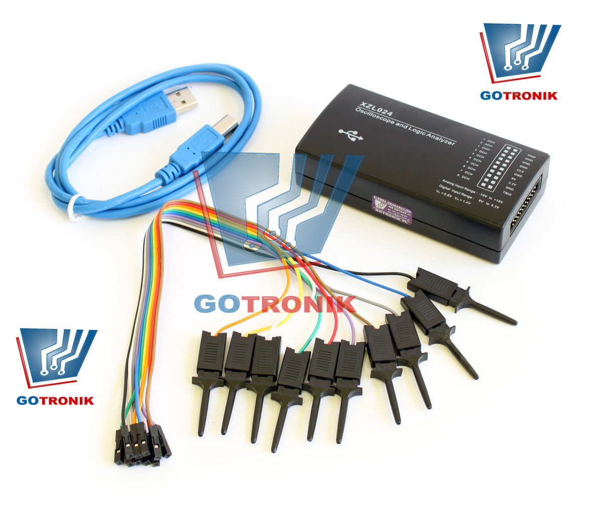
Zestaw zawiera:
-
interfejs XZL024 USB zgodny z USBee AX
-
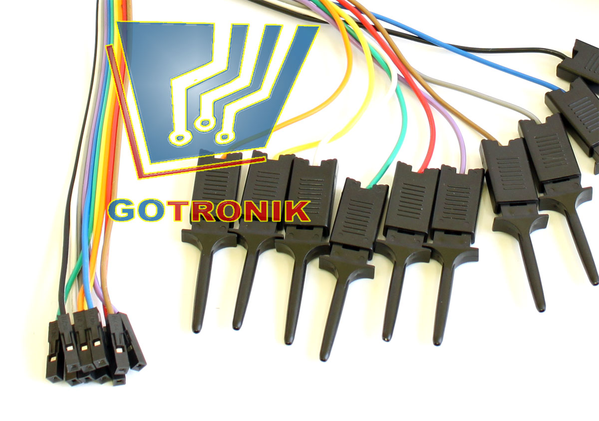
kabel połączeniowy
-
10szt. chwytaków pomiarowych na przewodzie
-
kabel USB
Zdjęcia:
|
Na naszych aukcjach odnajdziecie: |
||||||||
| Cyna do lutowania | ||||||||
 |
 |
 |
 |
 |
||||
| Zestaw "3 ręka" | ||||||||
 |
 |
 |
 |
 |
||||
| Groty | Izopropanol | Pasta lutownicza | Preparaty do elektroniki | Chemia do elektroniki | ||||
 |
 |
 |
 |
 |
||||
Wszystkie przedmioty wysyłamy w wspólnej przesyłce. |
||||||||

Ceny przesyłki podane są na początku strony. Proszę pamiętać o wypełnieniu formularza wysyłki po licytacji.
Koszty wysyłki zawierają 23% podatku VAT. Towary wysyłane są codziennie o godzinie 14.
Oferowany przedmiot jest nowy. Wystawiamy faktury VAT.
Zapraszamy do zapoznania się z naszą ofertą.

Telefon_1: (071) 351-10-31
Telefon_2: 501-814-982
Telefon_3: 507-011-247
E-mail: gotronik@gotronik.com
gg: 5476656
gg: 8342724
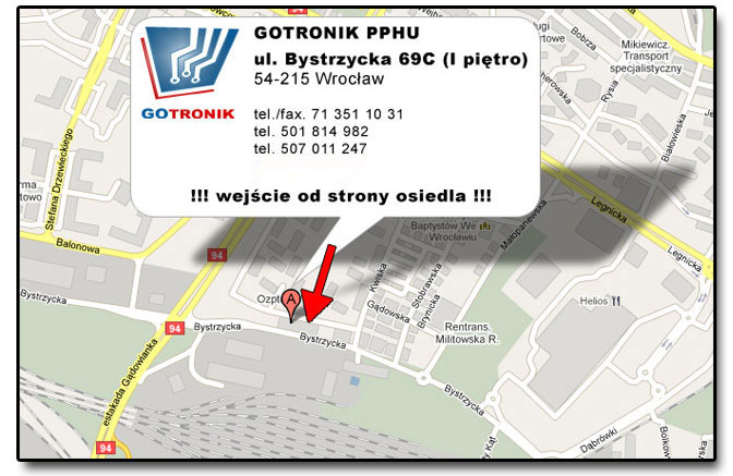
Adres:
GOTRONIK PPHU
ul.Bystrzycka 69c (I piętro)
54-215 Wrocław
Godziny otwarcia: patrz strona "o mnie"
Mapka dojazdu:
mapa Google
Oferowany sprzęt jest nowy.
Zapewniamy serwis gwarancyjny i pogwarancyjny, oraz wsparcie techniczne.
WYSTAWIAMY FAKTURY VAT.